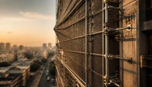
To protect pedestrians on busy city sidewalks, installing heavy-duty debris netting across your facade access staging is a non-negotiable safety requirement. However, wrapping an open metal framework in safety mesh fundamentally changes its physical aerodynamics. Instead of allowing breezes to pass harmlessly through the poles, the mesh catches the air, effectively turning your temporary structure into a massive sail.
If site engineers fail to accurately calculate the additional wind load on scaffolding with debris netting, a sudden monsoon gust can cause catastrophic structural overturning on any urban construction scaffolding Bangalore project. City sites face unique aerodynamic challenges, and treating a clad frame the exact same way as a bare frame is one of the most dangerous, yet common, mistakes a safety officer can make. The lateral pressure exerted against the building face multiplies significantly the moment you tie off that first protective screen.
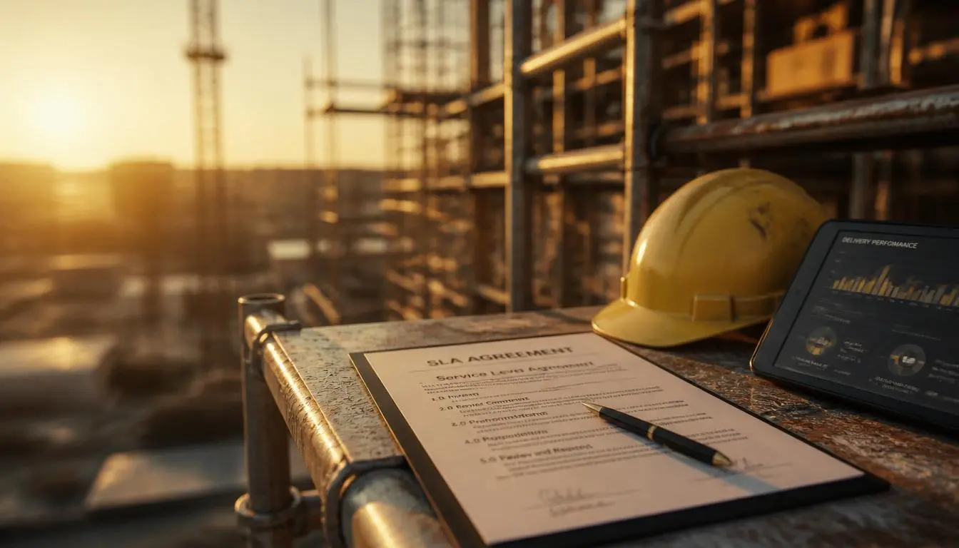
This technical guide breaks down the IS 875 Part 3 calculation standards, the direct impact of netting solidity ratios on aerodynamic drag, and exactly how to safely adjust your mechanical wall tie anchors to withstand the intense pressures generated by urban wind tunnels.
Key Insight: Protective safety netting is vital for catching falling materials, but it introduces a massive secondary hazard by catching the wind. Your staging anchor design must be proactively re-engineered to handle this invisible lateral force before the netting is ever installed.
The “Sail Effect”: How Cladding Alters Scaffolding Aerodynamics
Bare steel tubes offer very little resistance to moving air. When a gust hits an exposed framework, the breeze mostly flows right through the empty gaps. However, the moment you attach permeable safety nets to the exterior, the physics change entirely. You are essentially hoisting a giant sail on the side of your building.
This phenomenon creates an immense aerodynamic force pushing horizontally against the staging. As the lateral pressure builds against the mesh, it attempts to pivot the entire structure away from the facade, generating a dangerous overturning moment at the base. To accurately determine the wind load on scaffolding with debris netting, engineers cannot rely on the baseline weight of the steel alone; they must evaluate exactly how much of that air is being blocked.
Understanding Solidity Ratios and Drag Coefficients
The core metric used in any scaffolding debris netting wind load calculation is the material’s solidity ratio. This measurement represents the percentage of solid physical threads compared to the empty open holes in the mesh. For example, a dense privacy or dust net might have a solidity ratio of 70%, meaning only 30% of the wind can pass through safely.
As the solidity ratio increases, so does the aerodynamic drag coefficient ($C_d$). A higher $C_d$ means the netting absorbs more of the wind’s kinetic energy, translating it directly into intense windward pressure pushing against your vertical uprights. Consequently, a dense 70% shade net requires drastically stronger anchoring than a wide-weave 30% brick-guard net, even if the exact same staging framework is used underneath.
Key Takeaway: Never assume all safety netting performs identically in the wind. The denser the mesh, the higher the aerodynamic drag coefficient, which directly increases the lateral force trying to topple your temporary structure.
IS 875 Part 3: Wind Pressure Calculation Parameters for Staging
To engineer a safe, netted access structure, site planners must follow the legal and mathematical frameworks outlined in the National Building Code (NBC). Specifically, the IS 875 Part 3 wind load standards, working in tandem with the IS 3696 scaffolding safety guidelines India, dictate exactly how to evaluate lateral forces on temporary structures.
Unlike permanent concrete structures designed to stand for decades, temporary facade staging carries a different set of structural risk multipliers. However, the moment you attach debris netting, this temporary framework must be capable of enduring sudden monsoon gusts without buckling. According to standard Indian wind maps, the baseline basic wind speed for Bangalore is classified at 33 meters per second (m/s). Your engineering team must use this exact regional baseline as the foundation to determine your ultimate design wind speed before erecting a single vertical steel pole.
Step-by-Step Formula Variables ($k_1$, $k_2$, $k_3$)
If your safety team is figuring out how to calculate wind pressure on scaffolding nets, the process starts by taking that regional baseline wind speed and modifying it based on your specific site conditions. The IS 875 Part 3 code provides a clear formula to find the precise design wind speed ($V_z$) at any working height:
- Basic Wind Speed ($V_b$): The regional starting speed (e.g., 33 m/s for Bangalore sites).
- Risk Factor ($k_1$): A multiplier based on the lifespan of the structure. Temporary construction staging generally uses a lower risk factor (often between 0.71 and 0.76) compared to the standard 1.0 used for permanent high-rises.
- Terrain Roughness and Height Factor ($k_2$): This accounts for the physical environment surrounding your site. Scaffolding in an open field takes a heavier initial hit than staging shielded by dense urban skyscrapers. Importantly, this multiplier increases as your scaffolding builds higher into the air.
- Topography Factor ($k_3$): This variable adjusts the load if your project is located on a steep hill, ridge, or valley that might artificially accelerate wind speeds upward.
By multiplying these factors together ($V_z = V_b \times k_1 \times k_2 \times k_3$), site engineers can pinpoint the exact maximum wind speed the netted framework must endure, allowing them to calculate the true lateral pressure pushing against the facade.
Key Takeaway: You cannot guess wind resistance. Using the exact $k_1$, $k_2$, and $k_3$ parameters from IS 875 Part 3 ensures your anchoring strategy is based on legal engineering data rather than rough field estimates.
The Urban Wind Tunnel Phenomenon in Dense Bangalore Streets
While standard engineering codes provide a crucial baseline, the physical reality of building in a crowded city requires deeper localized awareness. When erecting high-rise facade access systems in closely packed commercial hubs, the surrounding architecture drastically alters natural airflow.
Large, densely built structures effectively block open wind paths. When a moving air mass hits a solid building face, it does not just stop; it is forced downward and sideways into the narrow alleys and pedestrian walkways below. This squeezing action rapidly accelerates the airflow, creating a powerful urban wind tunnel effect. Instead of a steady, predictable breeze, the air violently funnels through tight city grids, striking the lower tiers of your staging with concentrated, erratic force.
For example, in dense business districts, a moderate 15 m/s wind moving above the rooflines can easily amplify in speed at street level as it channels between two towering structures. If your staging is heavily clad in a high-solidity safety mesh, this tunneled air slams directly into the netting with nowhere to escape. The resulting pressure tries to tear the mesh away from the steel, pulling the entire framework away from the building.
Key Takeaway: The basic wind speed values pulled from a standard meteorological map often underestimate the localized pressure at ground level. Site planners must account for this tunneling acceleration to ensure the lower anchor points do not fail under sudden, concentrated lateral loads.
Re-Engineering Anchor Points: Adjusting Wall Tie Spacing
Because debris netting drastically amplifies lateral wind loads, relying on standard, un-clad tie-in patterns is a recipe for disaster. To keep the structure stable and counteract the sail effect, site engineers must completely re-engineer their anchor points, significantly tightening the overall grid.
Determining the correct scaffolding wall tie spacing for netted facades requires taking the total aerodynamic drag calculated under IS 875 and matching it against the maximum safe working load of your fixings. For an open framework, an industry-standard grid might only require one tie every 16 to 20 square meters of face area. However, once a high-solidity safety netting is attached, that spacing must be aggressively reduced. On heavily clad city structures, engineers frequently cut that spacing in half, installing a secure tie every 8.5 square meters or even closer to handle severe urban wind tunnels.
Beyond just the frequency of the ties, the quality of the connection is paramount. Heavy-duty mechanical wall ties must be drilled directly into the building’s structural columns rather than weak infill blockwork to maximize the ultimate pull-out strength. Furthermore, when attaching these ties back to your staging, always clamp the tubes as close as possible to the rigid node points where the vertical standards meet the horizontal cuplock ledgers. Attaching a tie to the unsupported middle of a ledger can cause the steel to bend or buckle under extreme tension.
Key Takeaway: Adding protective safety netting effectively doubles the lateral pressure acting on your temporary framework. To counter this invisible force, you must drastically increase the density of your mechanical tie grid, ensuring every individual anchor possesses the sheer pull-out strength to lock the staging firmly against the building.
Common Mistakes: High-Wind Scaffolding Failures
Even with top-tier modular equipment, a lack of specialized environmental planning can lead to catastrophic structural failure. The most frequent and dangerous mistake site managers make when preventing scaffolding collapse in high winds is treating a fully netted facade exactly the same as an open, bare-steel framework. This false sense of security leads to critical miscalculations in lateral load distribution.
Another major error occurs at the very foundation: relying on unanchored base plates or using inadequate kentledge (heavy dead weights) on ground-supported systems. When high-solidity netting catches a sudden urban wind gust, the resulting uplift force can lift unsecured base plates right off their sole boards, triggering a rapid sequence of structural buckling.
Higher up the facade, installation teams frequently ignore the condition of the host building itself. Drilling mechanical ties into old, crumbling masonry or weak brick infill instead of the primary structural columns drastically reduces the anchor’s holding power. When the severe overturning pressure peaks during a storm, these weak anchor points will simply rip out of the wall, allowing the entire netted framework to peel away from the building.
Key Takeaway: The strength of your staging is only as reliable as what it is physically tied to. Never anchor high-tension wall ties into weak masonry, and never assume your base plates will stay safely grounded without proper securement or adequate kentledge weight.
Action Steps: Your Debris Netting Safety Checklist
Before wrapping your urban site in protective mesh, your safety team must proactively verify that the underlying framework can handle the newly altered aerodynamics. To effectively manage the wind load on scaffolding with debris netting, strictly follow this 4-step execution checklist before allowing your crew onto the platform:
- Conduct a Pre-Site Inspection of Netting: Verify the exact solidity ratio of the mesh you plan to install. A dense 70% privacy net requires a vastly different engineering approach than a highly permeable 30% brick-guard net.
- Calculate Adjusted Wind Pressures: Apply the IS 875 Part 3 parameters to determine the exact lateral design force. Ensure your structural engineer specifically factors in the accelerated urban wind tunnel effect present on your street.
- Increase Tie-In Frequency: Discard standard, un-clad anchoring layouts. Redesign your grid to significantly increase the frequency of mechanical wall ties, ensuring every anchor connects as close to a rigid Cuplock node point as possible.
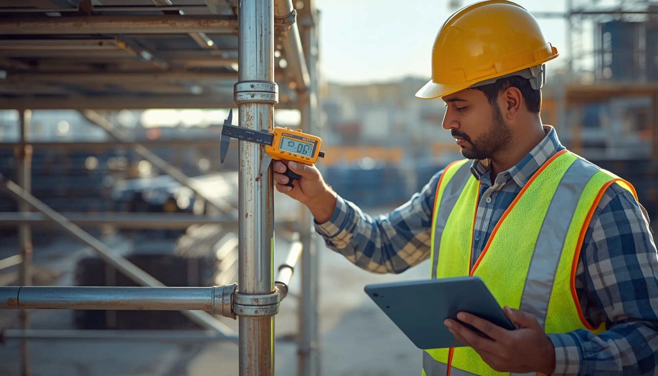
- Execute Pull-Testing Anchors & Secure Engineering Sign-Off: Never blindly trust the host wall. Physically conduct load pull-tests on a sample of your mechanical ties to verify their true hold strength in the concrete, and require a formal engineering sign-off before the netting goes up.
Mastering aerodynamic safety is just one component of building in tightly packed city grids. For a comprehensive look at maximizing your vertical reach without violating ground-level boundaries, explore our complete guide on Urban Construction Scaffolding Bangalore Design Layouts.
Contact Sri Kanakadri Scaffolding Today!
Phone: +91 9113276916
Visit our Google My Business Listing for Directions

About Sri Kanakadri Scaffolding Author – Sri Kanakadri provide Bangalore’s most reliable scaffolding on rental services, offering safe, cost-effective, and top-quality scaffolding rental solutions for all construction projects. With years of expertise, Sri Kanakadri Scaffolding is committed to delivering exceptional scaffolding on rental services in Bangalore that exceed client expectations. Our focus is on safety, quality, and affordability for every construction project. e specialize in scaffolding hire in Bangalore, offering reliable and cost-effective scaffolding rental solutions tailored to your needs. From construction scaffolding services to industrial scaffolding on rent, we ensure precision, safety, and efficiency in every project. Trust us for affordable scaffolding rentals that guarantee unmatched professionalism and reliability.