
Facade Protection: Calculating Wind Load Pressures for Debris Netting on Busy Streets
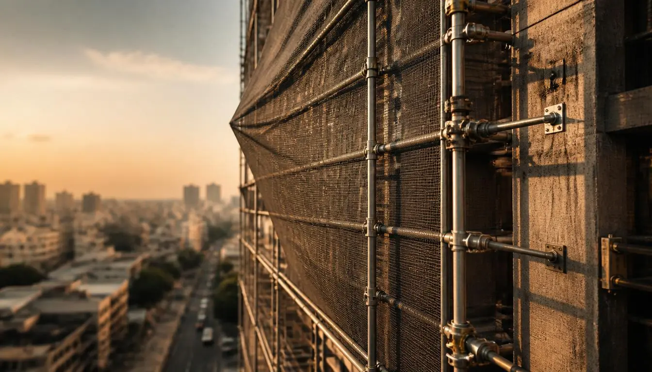
To protect pedestrians on busy city sidewalks, installing heavy-duty debris netting across your facade access staging is a non-negotiable safety requirement. However, wrapping an open metal framework in safety mesh fundamentally changes its physical aerodynamics. Instead of allowing breezes to pass harmlessly through the poles, the mesh catches the air, effectively turning your temporary structure into a massive sail. If site engineers fail to accurately calculate the additional wind load on scaffolding with debris netting, a sudden monsoon gust can cause catastrophic structural overturning on any urban construction scaffolding Bangalore project. City sites face unique aerodynamic challenges, and treating a clad frame the exact same way as a bare frame is one of the most dangerous, yet common, mistakes a safety officer can make. The lateral pressure exerted against the building face multiplies significantly the moment you tie off that first protective screen. This technical guide breaks down the IS 875 Part 3 calculation standards, the direct impact of netting solidity ratios on aerodynamic drag, and exactly how to safely adjust your mechanical wall tie anchors to withstand the intense pressures generated by urban wind tunnels. Key Insight: Protective safety netting is vital for catching falling materials, but it introduces a massive secondary hazard by catching the wind. Your staging anchor design must be proactively re-engineered to handle this invisible lateral force before the netting is ever installed. The “Sail Effect”: How Cladding Alters Scaffolding Aerodynamics Bare steel tubes offer very little resistance to moving air. When a gust hits an exposed framework, the breeze mostly flows right through the empty gaps. However, the moment you attach permeable safety nets to the exterior, the physics change entirely. You are essentially hoisting a giant sail on the side of your building. This phenomenon creates an immense aerodynamic force pushing horizontally against the staging. As the lateral pressure builds against the mesh, it attempts to pivot the entire structure away from the facade, generating a dangerous overturning moment at the base. To accurately determine the wind load on scaffolding with debris netting, engineers cannot rely on the baseline weight of the steel alone; they must evaluate exactly how much of that air is being blocked. Understanding Solidity Ratios and Drag Coefficients The core metric used in any scaffolding debris netting wind load calculation is the material’s solidity ratio. This measurement represents the percentage of solid physical threads compared to the empty open holes in the mesh. For example, a dense privacy or dust net might have a solidity ratio of 70%, meaning only 30% of the wind can pass through safely. As the solidity ratio increases, so does the aerodynamic drag coefficient ($C_d$). A higher $C_d$ means the netting absorbs more of the wind’s kinetic energy, translating it directly into intense windward pressure pushing against your vertical uprights. Consequently, a dense 70% shade net requires drastically stronger anchoring than a wide-weave 30% brick-guard net, even if the exact same staging framework is used underneath. Key Takeaway: Never assume all safety netting performs identically in the wind. The denser the mesh, the higher the aerodynamic drag coefficient, which directly increases the lateral force trying to topple your temporary structure. IS 875 Part 3: Wind Pressure Calculation Parameters for Staging To engineer a safe, netted access structure, site planners must follow the legal and mathematical frameworks outlined in the National Building Code (NBC). Specifically, the IS 875 Part 3 wind load standards, working in tandem with the IS 3696 scaffolding safety guidelines India, dictate exactly how to evaluate lateral forces on temporary structures. Unlike permanent concrete structures designed to stand for decades, temporary facade staging carries a different set of structural risk multipliers. However, the moment you attach debris netting, this temporary framework must be capable of enduring sudden monsoon gusts without buckling. According to standard Indian wind maps, the baseline basic wind speed for Bangalore is classified at 33 meters per second (m/s). Your engineering team must use this exact regional baseline as the foundation to determine your ultimate design wind speed before erecting a single vertical steel pole. Step-by-Step Formula Variables ($k_1$, $k_2$, $k_3$) If your safety team is figuring out how to calculate wind pressure on scaffolding nets, the process starts by taking that regional baseline wind speed and modifying it based on your specific site conditions. The IS 875 Part 3 code provides a clear formula to find the precise design wind speed ($V_z$) at any working height: Basic Wind Speed ($V_b$): The regional starting speed (e.g., 33 m/s for Bangalore sites). Risk Factor ($k_1$): A multiplier based on the lifespan of the structure. Temporary construction staging generally uses a lower risk factor (often between 0.71 and 0.76) compared to the standard 1.0 used for permanent high-rises. Terrain Roughness and Height Factor ($k_2$): This accounts for the physical environment surrounding your site. Scaffolding in an open field takes a heavier initial hit than staging shielded by dense urban skyscrapers. Importantly, this multiplier increases as your scaffolding builds higher into the air. Topography Factor ($k_3$): This variable adjusts the load if your project is located on a steep hill, ridge, or valley that might artificially accelerate wind speeds upward. By multiplying these factors together ($V_z = V_b \times k_1 \times k_2 \times k_3$), site engineers can pinpoint the exact maximum wind speed the netted framework must endure, allowing them to calculate the true lateral pressure pushing against the facade. Key Takeaway: You cannot guess wind resistance. Using the exact $k_1$, $k_2$, and $k_3$ parameters from IS 875 Part 3 ensures your anchoring strategy is based on legal engineering data rather than rough field estimates. The Urban Wind Tunnel Phenomenon in Dense Bangalore Streets While standard engineering codes provide a crucial baseline, the physical reality of building in a crowded city requires deeper localized awareness. When erecting high-rise facade access systems in closely packed commercial hubs, the surrounding architecture drastically alters natural airflow. Large, densely built structures effectively block open wind paths. When a moving air mass hits a solid building